
PopJack
Die young, after a long life.
I decided to document the way I installed my grip heaters. I bought SYMTEC brand grip heaters with the Rocker Switch and copied WILLIMAKIT's installation of the switch.
Because I'm a nut, I also wanted an LED to let me know when the heaters were on. This was not part of the kit, but was assembled from loose parts.
I used relays with my installation because of how I wanted to mount the switch.
Part 1 – Install heater elements
Step 1: Wash your motorcycle. This is an important step if you are going to take photos of the installation. Otherwise it is optional. I forgot this step.
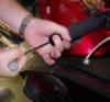
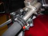
Step 2: Remove Bar Weights. Hold the bar weight with one hand while removing the bolt. The bar weights themselves do not screw in. One of the bar weights had vibrated out a bit, so I tapped the retainer back in using a smallish socket and a hammer.

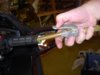
Step 3: Remove Grip puppies and Grips. I used compressed air blown up under the grips- worked like a champ. The grips were not damaged and I re-used them. After they were removed, I cleaned the plastic and metal surfaces with Acetone.

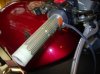
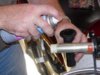
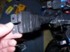
Step 4: Position and stick on heating elements. Position wires with an eye toward looming later.

Here's what it looks like applied:
Step 5: Reinstall Grips- I used liberal amounts of hairspray ($1.00 a can- what a deal!) as a lubricant and adhesive. It worked well for me. Spray the inside of the grips as well as the heaters. I also reinstalled my grip puppies. I used baby shampoo and water as the lubricant. This has the advantage of washing my gloves the first few times it rains.

Step 6: Reinstall bar weights.
Rinse and Repeat for other side.
Part 2: Install switch
Step 1: Remove two Phillips head screws and remove control house top. Inside I removed the clamp that holds the cluster on the bar.

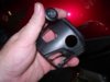
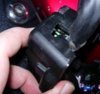
Step 2: I removed the switches from the top of the housing. Up to this point I was worried that water might get into the housing through the new switch. Obviously, it's not water tight.
Step 3: Drill hole for rocker switch. I drilled a ? inch hole and then used a pocket knife to enlarge it slightly for the switch to fit. The plastic is soft and easy to shape.

I also drilled a 1/8 inch hole for the LED.
Step 4: I soldered wires on the rocker switch and the LED (five total). I used 20 gage wire, that way the bundle was small and it was easy to route things in the control. This, however, also required relays to carry the "real power."
Each solder point was covered with heat shrink. The loose wires were then passed through a length of small heat shrink tubing. This provides good protection for the bundle and is easy to use.

Before buttoning everything up, I identified the loose ends of the wires with knots. (Center of switch, no knot, high side switch, three knots, etc.) After everything is covered, it all looks the same, so this saved me a lot of work.
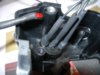
Step 5. I enlarged the slot in the lower part of the housing where the control wire exited. I routed the new wiring (in heat shrink) through this enlarged slot and then along with the cables down the handlebars.

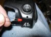
Step 6. Install the switch in place and glue in the LED. I used silicon adhesive on mine. Put dielectric grease on the exposed OEM switches, route the wires carefully and reassemble the controls. If you have a volt/Ohm meter, this is a good time to check that all the wiring does what you think it does.
Part 3. Routing Wiring and Relays
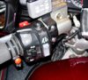
All of my relays (I use a lot) are located under the right hand faring. I removed the Tupperware necessary to access this area. All cables were carefully routed along routes defined by OEM and wire tied carefully to prevent movement.
(Note to self: Invest in Wire Tie Stock)
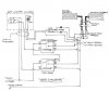
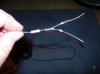
The LED I bought requires a load resister in series with it, or it will draw too much amperage and burn up. I was assisted in selecting the diodes I needed and load resister at the electronic store where I bought the relays. This is how it all looks:
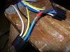
Step 1. Build an electronic device consisting of two diodes and a load resister. This "Y" allows voltage to be put in either leg without energizing the other leg. Figure out which side of the LED should be positive and negative. If you are as bad with this kind of stuff as I am, experiment for a while to make sure the diodes are oriented properly.
Step 2. If you've enjoyed yourself so far, you can test the installed LED without the required load resister and burn it out. You then get to do a lot of it over.
Step 3. Route switched power to the area of the relays and find a good ground. I use a switched circuit breaker box under the seat for power.
Step 4. Hook up relays. For this project, I used sockets. I normally use standard spade connections and heat shrink. I'm not sure if I'll use sockets again or not, I don't think it's more secure and it's harder to seal up things.
I use the same ground to hook up the ground wire on the Heater units.
I spliced the LED leads (the two legs of the little wire man) into the power leading to the heaters themselves- not to the leads from the switch. This way when the LED is on I know that the relays are working properly.
Step 5. Seal the whole mess up. I'm not really proud of how this one looks, but every connection is soldered and sealed. Because of the way I did it, there was no good way to use heat shrink. I use heavy duty electrical tap (88) to seal up, along with silicon where necessary. I am very picky about my tape!

Step 6. Tuck everything in place, double check the looming, put the Tupperware back on.
Part 4: Enjoy.
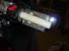
Sit on your bike in the garage, make spaceship noises with the key on and turn on your grip heaters. Watch the cool little LED light up and tell you that all is right with the world. Feel your hands get warm. Begin contemplating your next Farkle adventure.

EDIT: It's been 18 months since I installed these heaters. They work very well and I have REALLY enjoyed having them. The little LED works great too. Someone noticed I had a throttle lock and ask if it interfered. The answer is "no." I never thought about the throttle lock being an issue, I might have worried, but as it turns out there was no conflict at all. This was a wise investment- one of my favorite farkles.
Because I'm a nut, I also wanted an LED to let me know when the heaters were on. This was not part of the kit, but was assembled from loose parts.
I used relays with my installation because of how I wanted to mount the switch.
Part 1 – Install heater elements
Step 1: Wash your motorcycle. This is an important step if you are going to take photos of the installation. Otherwise it is optional. I forgot this step.
Step 2: Remove Bar Weights. Hold the bar weight with one hand while removing the bolt. The bar weights themselves do not screw in. One of the bar weights had vibrated out a bit, so I tapped the retainer back in using a smallish socket and a hammer.
Step 3: Remove Grip puppies and Grips. I used compressed air blown up under the grips- worked like a champ. The grips were not damaged and I re-used them. After they were removed, I cleaned the plastic and metal surfaces with Acetone.
Step 4: Position and stick on heating elements. Position wires with an eye toward looming later.
Here's what it looks like applied:
Step 5: Reinstall Grips- I used liberal amounts of hairspray ($1.00 a can- what a deal!) as a lubricant and adhesive. It worked well for me. Spray the inside of the grips as well as the heaters. I also reinstalled my grip puppies. I used baby shampoo and water as the lubricant. This has the advantage of washing my gloves the first few times it rains.
Step 6: Reinstall bar weights.
Rinse and Repeat for other side.
Part 2: Install switch
Step 1: Remove two Phillips head screws and remove control house top. Inside I removed the clamp that holds the cluster on the bar.
Step 2: I removed the switches from the top of the housing. Up to this point I was worried that water might get into the housing through the new switch. Obviously, it's not water tight.
Step 3: Drill hole for rocker switch. I drilled a ? inch hole and then used a pocket knife to enlarge it slightly for the switch to fit. The plastic is soft and easy to shape.
I also drilled a 1/8 inch hole for the LED.
Step 4: I soldered wires on the rocker switch and the LED (five total). I used 20 gage wire, that way the bundle was small and it was easy to route things in the control. This, however, also required relays to carry the "real power."
Each solder point was covered with heat shrink. The loose wires were then passed through a length of small heat shrink tubing. This provides good protection for the bundle and is easy to use.
Before buttoning everything up, I identified the loose ends of the wires with knots. (Center of switch, no knot, high side switch, three knots, etc.) After everything is covered, it all looks the same, so this saved me a lot of work.
Step 5. I enlarged the slot in the lower part of the housing where the control wire exited. I routed the new wiring (in heat shrink) through this enlarged slot and then along with the cables down the handlebars.
Step 6. Install the switch in place and glue in the LED. I used silicon adhesive on mine. Put dielectric grease on the exposed OEM switches, route the wires carefully and reassemble the controls. If you have a volt/Ohm meter, this is a good time to check that all the wiring does what you think it does.
Part 3. Routing Wiring and Relays
All of my relays (I use a lot) are located under the right hand faring. I removed the Tupperware necessary to access this area. All cables were carefully routed along routes defined by OEM and wire tied carefully to prevent movement.
(Note to self: Invest in Wire Tie Stock)
The LED I bought requires a load resister in series with it, or it will draw too much amperage and burn up. I was assisted in selecting the diodes I needed and load resister at the electronic store where I bought the relays. This is how it all looks:
Step 1. Build an electronic device consisting of two diodes and a load resister. This "Y" allows voltage to be put in either leg without energizing the other leg. Figure out which side of the LED should be positive and negative. If you are as bad with this kind of stuff as I am, experiment for a while to make sure the diodes are oriented properly.
Step 2. If you've enjoyed yourself so far, you can test the installed LED without the required load resister and burn it out. You then get to do a lot of it over.
Step 3. Route switched power to the area of the relays and find a good ground. I use a switched circuit breaker box under the seat for power.
Step 4. Hook up relays. For this project, I used sockets. I normally use standard spade connections and heat shrink. I'm not sure if I'll use sockets again or not, I don't think it's more secure and it's harder to seal up things.
I use the same ground to hook up the ground wire on the Heater units.
I spliced the LED leads (the two legs of the little wire man) into the power leading to the heaters themselves- not to the leads from the switch. This way when the LED is on I know that the relays are working properly.
Step 5. Seal the whole mess up. I'm not really proud of how this one looks, but every connection is soldered and sealed. Because of the way I did it, there was no good way to use heat shrink. I use heavy duty electrical tap (88) to seal up, along with silicon where necessary. I am very picky about my tape!
Step 6. Tuck everything in place, double check the looming, put the Tupperware back on.
Part 4: Enjoy.
Sit on your bike in the garage, make spaceship noises with the key on and turn on your grip heaters. Watch the cool little LED light up and tell you that all is right with the world. Feel your hands get warm. Begin contemplating your next Farkle adventure.
EDIT: It's been 18 months since I installed these heaters. They work very well and I have REALLY enjoyed having them. The little LED works great too. Someone noticed I had a throttle lock and ask if it interfered. The answer is "no." I never thought about the throttle lock being an issue, I might have worried, but as it turns out there was no conflict at all. This was a wise investment- one of my favorite farkles.
Attachments
-
 11587.jpg33.2 KB · Views: 207
 -
 11584.jpg26.7 KB · Views: 103
 -
 11592.jpg27.2 KB · Views: 198
 -
 11588.jpg19.6 KB · Views: 96
 -
 11589.jpg24.5 KB · Views: 110
 -
 11576.jpg21.2 KB · Views: 63
 -
 11577.jpg23.3 KB · Views: 63
 -
 11578.jpg21.5 KB · Views: 63
 -
 11580.jpg26.6 KB · Views: 64
 -
 11582.jpg34.9 KB · Views: 62
 -
 11583.jpg22.1 KB · Views: 63
 -
 11585.jpg27.1 KB · Views: 64
 -
 11586.jpg23.9 KB · Views: 64
 -
 11590.jpg55.8 KB · Views: 65
 -
 11591.jpg24.8 KB · Views: 63
Last edited by a moderator:
