Help with Givi Top Case brake light

ScottST

Site Supporter
Joined
Aug 25, 2024
Messages
44
Age
61
Location
Indiana
Bike
2004 ST 1309
Please don’t tell IGOFAR I’m messing with the electrical on my beloved ST.

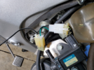
I have the tail lights off and have the wires exposed but can’t figure out which wires to connect the Givi wires too.

I’ve used my mutimeter and pushed the brake pedal with the Givi wires hooked up multiple ways (and yes, they work connected directly to 12V) but I can’t get them to come on when I hit the brakes….Help!
 
So I’ve played with my givi 47. It has a set up that used a contact when closing the case along with a contact point on the base and it failed miserably. So eventually I hard wired the case and added leds to the reflector bar. Then basically used connectors to the source. The wires are tapped from the rear brake and running lights. I ran leads and put a color coded connector to match the leads from the case. Also it’s got a flasher set up for the brake.
That being said leds are specific on connecting positive and negative to work. To determine such I used a 9volt battery to identify which is such.
It’s really up to you but I found hard wiring worked best and the lights perform as expected.

PS IGOFAR hates the electronics side of any bike. He has a point if you don’t understand it don’t mess with it. Me I’m a McGyver at heart
 
For the motorcycle the rear lamp assembly wiring colours are as follows;
Rear running lamp wire are black/brown.
Rear stop lamp wires are light green/yellow.
Right turn signal lamp wire is solid light blue.
Left turn signal lamp wire is solid orange.
All lamp ground wires are solid green.

I don't know what colours the Givi wiring harness uses but that is easy enough to figure out by applying power to each one to see what illuminates. Once that is figured out it is simply a matter of connecting the Givi wire to the correct motorcycle wire based on function. This is a simple 12V+ and 12V- system so if the motorcycle lights all work properly then the Givi wires are not connected to the motorcycle wires.

The above assumes that the motorcycle lights all work properly, that the ground wires are providing a good ground, and that the motorcycle brake lights illuminate when both the brake hand lever and the foot pedal are operated. i.e. The brake light switches are working and are sending 12V+ to the rear bulbs.

Also make sure that your motorcycle battery has not been depleted while you have been working on this. I don't know what type of bulbs are in the Givi case but if they are LED some LED bulbs will not illuminate below a certain voltage. Maybe perform the test with a battery charger connected to the motorcycle battery.
 
Please don’t tell IGOFAR I’m messing with the electrical on my beloved ST.

I have the tail lights off and have the wires exposed but can’t figure out which wires to connect the Givi wires too.

I’ve used my mutimeter and pushed the brake pedal with the Givi wires hooked up multiple ways (and yes, they work connected directly to 12V) but I can’t get them to come on when I hit the brakes….Help!
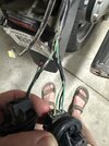
Light negative to bike's solid green wire, light positive to bike's green wire w/yellow stripe.
 
I recommend it be wired in a way to protect the OEM circuit from overloading or short to ground protection, especially if the box will be removed and installed frequently.
 
........ It has a set up that used a contact when closing the case along with a contact point on the base and it failed miserably. .

Am just looking at the same.

I have 12V at the contact points on the GIVI plate and the lights are working if directly powered, but no luck when the box is installed. Used to work just fine,
 
When I wired my Givi box with brake lights, I chose not to cut or Positap, Scotchlock, or perform any type of wiring surgery.

I located the connector to the rear brake light switch, just below the rear of the right cylinder head and constructed a short passthru wire harness with a pair of male/female Hitachi connectors to insert in between the OEM connectors. I then ran the wires up along the right side frame rail above the battery and back toward the tail section where I inserted a pair of bullet connectors to allow easy removal of the tailsection and Givi rack without going all the way down to the brake light switch.

Zero wires cut/spliced/tapped into, and I can return it back to OEM with no evidence it was ever there.

Every electrical mod you do would benefit from have a set of connectors and a proper wire crimper. For less than $40 you'll have all the components to make this and nearly nearly every electrical mod you make in the future look like OEM, and more important, be significantly more reliable in the long run.

Just my 2¢

1750025520622.png

1750025575463.png

Glarks 700Pcs 2.8mm 2 3 4 6 9 Pin Plug Housing Pin Header Crimp Electrical Wire Terminals Connector and 30 Sets 4mm Car Motorcycle Bullet Terminal Assortment Kit

Crimping Tool with Ratchet, Ratcheting Wire Crimper Tool for Open Barrel Terminal Connectors, Electrical Crimping Tool, Crimping Pliers for 20-14 AWG
 
Thanks everybody. I spliced into the green/yellow strip wire and grounded the black wire from the box to the frame.

Working like a charm.

Thanks again! Extra brake lighting is always a good thing!
 
Good solution. When I did mine, I did think about going to the brake light switch connector. For some reason, I thought that the brake light switch was a switch to earth. I didn't check.
But in any case I wanted brake light power and tail light power to make my Honda top box LED tail light bar act as a tail / stop so I spliced into the harness leading to the tail stop.

Soldering the splice is not something that Honda does in the harness. Solder corrodes and the joint is brittle. But my splice was soldered. Rub silicone grease along the joint and slide heat shrink tube over it. Then tape two lengths of cable tie alongside the joint to act as a splint - to prevent one side of the joint moving against the other.

I cannot find any sources in the uk that supply crimp connectors for splicing - like the ones that Honda use. I'm obviously looking in the wrong place.
 
I cannot find any sources in the uk that supply crimp connectors for splicing - like the ones that Honda use. I'm obviously looking in the wrong place.

This is a reasonable option. Those butt splice crimp terminals are part of this ring terminal kit. Haven't used one of them yet but I have a couple of ideas where these would work nicely. You'll have to provide your own insulation/heat shrink tubing.

Hilitchi 605Pcs Non-Insulated Open Barrel U Shaped Ring Crimp Terminals Assortment Kit (M3 M4 M5 M6 M8 M10, TC-1, TC-T)

1750057615080.png
 
I cannot find any sources in the uk that supply crimp connectors for splicing - like the ones that Honda use. I'm obviously looking in the wrong place.

As an option, EasternBeaver can customize a splicing assembly for you.

They sell splicers for bikes that have accessories plugs but can put together whatever wiring you need.
 
Now, can anyone tell me how you stop the consarned ball bearing from slipping out constantly while trying to thread a new lock cylinder and re-apply the little metal locking clip?

Stupid clumsy fat fingers.......

:doh1:
 
Back
Top Bottom