Re-baking my ST1300 (Almost full redoing)


I really don't know why didn't find it having the thread such a simple name. I think I used the wrong words when searching. Thank you.
 
Well, yesterday I put the coolant (I'm still missing the 6mm to 8mm adaptor for the hose going from the radiator to the "T" that then goes one to the throttle body and the other to the right bank, so I plugged them closed just for protecting a bit the engine as I was doing some check-up) and it has a massive leak. The coolant comes from the small hole all we know, and at the first I thought about the seal of the pump, BUT I saw some leaking coming from the very top, probably from the thermostat casing, so I have to remove again the throttle body and check up all there. Probably I'll use a cheap 4 € endoscopic camera I have to check the leak source before dissasembling. Only leaks when the engine is running and revving. After being sure nothing leaks there, I'll be able to assure if anything leaks at the coolant pump.

I'll try to post all the work done these days of silence I've had. Another great thing worth saying beforehand is that I checked the error codes from the MIL and it has like 7 or 8 different codes, all from the throttle body harness wiring, maybe because it was turned on without those wires plugged. After erasing codes and testing the engine a bit, and revving it and so on, the MIL is not coming ON again, such a pleasure! So far just by now...
 
Last edited:
Hello. Let's go with the detailed process.

My main state of tought about the issue:

1749731147918.png

So, even I want a good protocolary thing following the workshop manual, my main focus is in getting things done and working PROPERLY, with the best or at least equal results, despite being protocolary not always correct. EG the footrest thing cited before. They are not the original for the ST1300, but they WORK and have a perfect fit. And cost around 100 € less than the original ones. GOOD ENOUGH and maybe better but for sure EQUAL solution.

I'll explain or show things in chronological order, as it's too much to get it better presented.

I cleaned these things. I clean almost everything with gasoline, maybe along the thread you could notice the brain damage taking place because the fumes inhaled all these months. I use a special soapy degreaser that dryes my skin as hell, to the point that I feel my own hand leather as a glove instead of part of me. Rubber gloves makes things worse, I tried that.

After a nice cleaning with toothbrush and other things embeded with gasoline, I oil it or grease it and put it back together. Just like that most of the problems in my devices get solution with just a good cleaning. Things getting old is rare to me, as most of the "old" thing goes away with cleaning and lubricating. Maybe some adjustment or part replaced and BOOM, just like new.

1749731502033.png

1749731524971.png

1749731539785.png

1749731562887.png

1749731581717.png

1749731618208.png


1749731633328.png


I do oil or grease it thinking about two things. NOT making short circuits with the used lubricant and protect it from corrosion and dirt the best availabe way.

I also glue some screws, depending on a lot of circumstances, but always if it was glued before.

Now these buttons and levers work like new.
 
Last edited:
I deeply cleaned the thermostat, changed its o-ring gasket, etc. Sadly I didn't take a picture of it to have the "before", but it looked really bad. I'm glad it wasn't corroed.

1749732658821.png


Now the lower engine wiring harness. I explained before the "science" behind it, now I'm showing the work without too much explanation about the deep reasons of everything.

1749732098691.png

Destroyed, just a bunch of cremated wiring dead body parts.

Well, for my exciting surprise, all connectors were on aliexpress, everyone. ALL. OF. THEM. And better a new chinese than a brittle, broken japanese one, sadly. I tried to rescue the old connector without success, really even with the most delicate movements they got broken like candy.

So, the new ones, missing the big one that arrived later:

1749732263315.png
I used fiber glass covered wires, with special rubber, for bearing the heat. And I soldered the terminals in some connectors, as some of them for some reason were coming off easily. Just a bit of tin and all was perfectly fine, having care of not flooding the terminal as it could get broken because the hard metal inside the "spring" that makes contact with its counterpart. I found this to be weird, as usually crimping them is enough. But these wires are oversized for those terminals and I pulled them maybe too hard when creating this thing, so I just soldered them to be sure.
I made the wires from the engine to the main connector, leaving as explained before a bit of extra part of wire, to do later the main connector with all of them and not have any wire too short. The only wires I didn't do that way were the knock sensors, I used the exact same long of wires, just to be sure the signal arrive at the correct time and are not delayed or so. I'm also sure this wouldn't affect the thing, but it's a good principle to follow anyways.
1749733161317.png
Up this line you have the copper eye for the neutral switch, crimped, soldered and covered with thermic tube with glue (notice the glue over the sleeve), with that fiber glass heat resistant wire, twice the gauge than the original one. For wires usually is better higher gauges than the original, but never less than it. Having that in mind you can modify things if needed. I prefer bigger wires because they bear better the heat than the thinner ones like the originals.

HOW TO put a new connector:
Prepare your wire. This one is a shielded one, is for the knock sensor. The shield should go to the mass, to negative. I saw in other posts that connecting this shield to a better negative than the one in the main connector gets rid of some issues, so I took my chances and make an extra wire to connect to the block of hydraulic connectors for the brakes that is behind the engine, inside the chasis:
1749733374908.png
Then you put the small silicone thing and the terminal:
1749733515068.png
Then you crimp it with the respective tool. This is an oversized wire for this terminal, so even it seems good, its a bit off than expected:
1749733557138.png
I put some thermic sleeve for the sake of elegance and getting things sturdier:
1749733607405.png
All connectors have a small nail that stop the terminal from getting out of it. You have kits of tools for getting this thing out for 2 or 3 euros on internet:
1749733665428.png
First you put the terminal in, then the blue cap from the front side. This blue cap has another kind of nail that holds in place the first nail that get the terminal stuck inside. It's kind of double checking that the thing is not going anywhere.
As you can see, I covered the thing with thermic aluminium tape. Most of the heat comes as IR radiation, and aluminium tape deflects it 100% or close to it. maybe 90% of the damage to the wires can be avoided with this tape, I'm sure. So all the thing you'll see is because of that.
1749733836812.png
I'm really satisfied with the results. I'm missing some physical restraining for the wires, as I just used that aluminium tape and I'm trusting this fiber glass wires. In the future I'll be checking it out, if it needs better protection I'll put it on no doubt ASAP.
1749733914625.png
Notice that I'm bringing the wires to the main connector and leaving some extra longness.
Comparison between the old and new ECT connector:
1749734058307.png
1749734073033.png
Yeah, I was ready to "use" that broken connector.
In this one I used a braided thermal protection before the aluminium tape. I really like this braided one.
1749734163401.png
Here you have a lot of wires with the aluminium tape:
1749734202310.png
1749734212251.png
Almost all the small coolant hoses are new, specifically the 6 and 8 mm. From the oil filter to the radiator and the thermostat housing.
I got the ECT from aliexpress, but for some reason is not working on the specified range. I'm working on the refund of it. It's like for another model of bike. It works, but not for mine. I did the heat test and so on. Mine is working well despite being cooked, but it's what I have, maybe I'm changing it in the future.
1749734375608.png
I noticed that for the main connector YOU HAVE TO LIFT THE TERMINAL, not some plastic nail, in order to get it out. Really important to have in mind that. And you have to be very carefull when putting the plastic cover inside it, as if there's some of the "nails" not full in it will not fit, so if you press it too much you broke it. Mine went well but took a bit of time to put it together properly. The finished big connector:
1749734516156.png

I'm doing another post so this one doesn't get too big.
 
Last edited:
Leon,
Thank you for an amazing detailed documentation of your restoration! Your level of detail and meticulousness is inspiring! NOTHING stopped you!! You are a master!
/r
Brad
 
I forgot about some interesting thing. The bike came with some nice heated handle covers (I don't know the name of them, please let me know how the heck you name this). But they were pretty loose and they tried glueing them with a lot of crappy things. It was really a mess. I cleaned it, even sanded it a bit and tried different things to get them well fixed. Nothing worked better than some thing that we call in Spain "chemical stud". It's not so expensive, like 15€ the 500 ml of thing, sold in a bottle for the common silicone glue gun. It's kind of a two components resin with kinda sand in it, used for when you destroy your wall trying to hang something, or your wall is weak or things like that. I put just a bit of this thing, very thin layer of it inside and outside the thing, after a good cleaning and some soft sanding, and the thing is so hard that I'm sure that I'll have to break it to take it out if needed in the future. From a completely loose to the most hard stuff I got regarding handlebars. Maybe could be useful to you in the future. This kind of sand-resin glue is amazing.
Also I printed some small red part in my 3D printer to fill a small gap left there, that red ring:
1749735212958.png
1749735224297.png
 
I'm posting now how I fix broken wires close to connectors. In this case the ABS sensor connector from the rear wheel. Wires were broken, as usual, so I soldered a couple inches more because I also noticed they were somehow short.

First, I cut the wire having in mind that I'm soldering close to the connector:

1749737966882.png

Then I remove the cap inside to access the nails stopping the terminals from coming out:
1749738024833.png
And using a proper tool o a slim, hard wire, I free the terminals from its nail to take it out cleanly:
1749738068396.png
I solder the extra wire to each one, protecting them with double thermal sleeve:
1749738146094.png
First I protect the soldering zones, then the group, overlapping the original sleeve:
1749738183732.png
Finished work:
1749738198378.png
 

Attachments

  • 1749738129062.png
    1749738129062.png
    1,022.7 KB · Views: 1
I wanted an extra air intake for the alternator. As I think I said before, here in Spain you have around 4 ST1300 on sale for each one you have working properly, all of them with a broken alternator. SO, the weak point of this bike is clearly the extreme heat it gifts to its hated/heated alternator. I'm doing an extra ventilation to that zone, whatever it takes. By now I put this metal pipe straight to the alternator zone, a bit back from it, and maybe I'm printing a scoop to catch air inside it from the front of the bike. I know it will crash with the air intake, but maybe I'm cutting that later so it fits properly. that metal pipe is staying there. By now.

1749738422262.png

1749738441431.png

1749738450739.png
 
And now, something I really enjoyed more than expected. My very first experience copying transponders.

Here copying a key is like 50€ and taking the bike to a workshop. Enough reason is for me that another dude would put its paws over MY bike. That's a full NOPE to me. So I checked the chip inside my very only key for my bike and was this. The picture was taken with a microscope for electronics that you can find for 5 euros in AliExpress or anyone of those stores:
1749739477356.png


SO, I bought this stuff from AliExpress after checking properly that would fit my bike:

1749739231593.png
1749739266717.png
1749739276628.png
1749739290160.png

A (now) friend of mine copied the physical key following some indications of mine as the key was a bit twisted and in bad shape, and then I recorded some random information to one of the chips, and followed the procedure to sync the new keys to the bike. I'm posting my procedure with some extra indications that the original post I've seen here in ST-owners.com didn't have and were somehow important:

- Disconnect the Ignition Pulse Generator from the plug close to the battery, with yellow and white/yellow wires, on the wire harness.
- Connect 12V to those wires, respecting that the + must go to the full yellow wire.
- Put the key in the bike and turn it to ON, having the red switch to RUN (important thing).

- Disconnect the + from the IGP connector for more than 2 seconds, connecting it back again before 5 seconds (before the HISS light turns off, which will turn ON after disconnecting it).
- Take out the original key and put it far more than one foot (to be sure) from the transponder reader.
- Put the new, blank key and turn it to ON.

- Take that out and put another new, blank key and turn it to ON.
- Repeat to max 4 keys.
- After taking out the last one, disconnect the 12V from the IPG connector, put back the connector to the IPG.

- Test the keys to make the engine run.

It was a neat surprise to find out that the motorcycle erase and record and blocks the blank chips. I bought the Zed-Bull for nothing. Was not necessary. Anyways I have now a new toy to play with, a Zed-Bull. And a couple crisp new keys working for less than 50 €.

You'll love the key switch work I made yesterday. I'm showing you that later.
 
Now we are going on with this gentleman:

1749740560637.png
1749740573753.png

Thing was NASTY.

1749740597185.png

For the good or for the bad, I didn't notice that I shouldn't dissasemble the white painted parts. So after messing just a bit, it was too late, so I messed it up fully to the deepest and I'm fixing it later. That process may be really useful here for others to know, how the heck I'm thinking about fixing that. I know the process that the workshop manual says, but this is more concerning as it needs to have them pretty good synchronized before doing the other thing, and thet first one of the small ones should also be put on place with some special consideration, that's the data I will find and show you here.

As usual, gasoline:
1749740819354.png

Should be "broken" but looks fantastic after a good cleaning.
1749740852905.png

1749740867506.png
1749740876306.png
1749740885711.png
1749740893011.png


About the thermostatic thing it has for when it's cold, it surprised me it was really thermostatic. I was expecting a pressure thing, as when the coolant get hot it gets pressure and you can use that to know when its cold or not.
1749740966877.png


I put some thermal paste over it, just to be sure:
1749740993863.png
I didn't expect for Honda to go this far, but they did. A damn miniature ball bearing in the rocker arm:
1749741026159.png

1749741044996.png

After that I assembled it back, glueing the screws that should be glued, torquening them to the generic torque for those screws, and visually putting it in place so it has a good start until full synchronization is done. Also all was completely cleaned and lubricated then with lithium grease and 10W40 oil, depending on which part. The change in smoothness of movements was noticeable. When I finish the coolant thing fixing I'm doing the throttle body work, until then I cannot doing it properly because I cannot get the bike to the correct temperature.

Must mention that the black paint, probably teflon, was full broken. I didn't see that "molibdenum" the workshop says, maybe was that paint.
 

After one thousand and one day from receiving it and 248 days of work, the engine started up the past June 09 around the 23h. I wanted to post the video of that first start-up, but sadly the page don't support mp4 format.
 
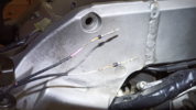
All them but referring to the alternator cooling duct. I wondered about that after seeing someone installing insulation around the entire V cavity to reduce heat on rider
"How's the alternator going to survive?"

I think the same. I'm also considering installing a thermometer there so I can know the real temperature in there all the time. It's just 4 more euros to get that. The previous owner of this bike did exactly that, make an oven for the alternator in the filling up all the thing with thermal insulation.
 
This part I'm sure you'll like it more than the others. Maybe.
1749742170908.png

Again, the thing was NASTY.
1749742196018.png

1749742206542.png


Thing is as usual, a good cleaning and a good greasing/oiling. That's it, it works like a charm.
1749742259427.png
1749742424124.png

This thing, with its plates, is what you can modify with a mini-drill so you can adapt any key to it, or it to any key. You can check if the key is OK and modify it. The trick is that all the plates should be in there, so until some point you can cut them, or re-arrange them. That's how I modify keys or locks if necessary.
 
For the last but not the least, after plugging it everything in there and erasing the fault codes, the MIL it's not getting ON again. Even after some seconds over 2k rpm. So the wiring is OK.

The ABS light is another story and I'm checking that later, after fixing the hoses and putting the DOT4 in and so on.


1749742584057.png
 
Last edited:
Back
Top Bottom